In the operation of industrial water treatment systems, membrane performance degradation is an inevitable thermodynamic phenomenon. The accumulation of particulates, colloids, organic matter, and mineral precipitation on the membrane surface creates a significant layer of hydraulic resistance. This is where the RO membrane chemical cleaning procedure becomes a critical intervention that differentiates between a long-lasting system and one that experiences premature failure.
As engineering practitioners at PT Mizui Osmosa Teknovasi, we often encounter a fatal misconception in the field: operators relying solely on regular hydraulic flushing. In reality, the chemical bonds between foulants and the membrane’s polymer surface require bond-breaking through specific chemical reactions, whether through hydrolysis, solubilization, or chelation. This article will thoroughly explore the Clean-In-Place (CIP) methodology based on international technical standards.
Dissecting the Anatomy of Fouling: Why Backwashing Alone Is Not Enough?
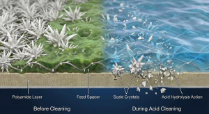
In conventional filtration systems, backwashing might be sufficient to dislodge dirt. However, in Thin-Film Composite (TFC) Polyamide membranes, the fouling mechanism occurs on a molecular and microscopic scale. Fouling is not just an accumulation of dust; it is an adsorption layer that alters the membrane’s surface characteristics.
Normalized Data Analysis: When is the Right Time to Perform CIP?
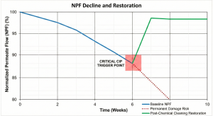
The decision to initiate RO membrane CIP cleaning must not be based on intuition or a mere calendar schedule, but rather on normalized data. Raw operational data (such as flow and pressure) are often biased because they are influenced by fluctuations in temperature and feed water salinity.
Referring to the ASTM D4516 standard, performance parameters must be normalized to separate operational variables from membrane condition variables. The absolute technical indicators to initiate cleaning are:
-
Normalized Permeate Flow (NPF): A decrease of 10-15% from the baseline condition (initial operation or post-previous cleaning).
-
Normalized Salt Passage: An increase in salt permeability by 5-10%.
-
Differential Pressure (dP): An increase in dP (Delta P) by 15% between stages or across the total vessel.
Delaying the response to these parameters can lead to the phenomenon of irreversible fouling, where foulants have been compressed into the membrane’s pore structure or caused physical channeling on the membrane leaves due to extreme dP.
Inorganic Scaling vs. Organic Biofouling: Different Enemies
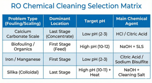
The RO membrane chemical cleaning strategy relies heavily on identifying the type of pollutant. We cannot use a single “silver bullet” for all membrane ailments.
-
Scaling (Inorganic): Occurs when the concentration of dissolved salts (Calcium Carbonate, Calcium Sulfate, Silica) exceeds the solubility limit at the membrane surface due to the Concentration Polarization phenomenon. This forms hard, sharp crystals that can tear the polymer layer.
-
Fouling (Organic & Biological): Involves bacteria, algae, and natural organic matter (NOM). The formed biofilm is sticky (slime) and protects bacterial colonies from water flow, causing a drastic increase in dP in the lead element (the first element).
The Chemistry of Cleaning: Choosing Precise Chemical Recipes
The effectiveness of RO element chemical washing is determined by an understanding of stoichiometry and chemical reactions. At PT Mizui Osmosa Teknovasi, we adopt the industry-standard two-stage approach: High pH for organics, followed by Low pH for minerals. This sequence is crucial; performing acid cleaning first on a membrane with biofouling can cause the biofilm layer to harden (coagulate) and become permanent.
High pH Cleaning (Alkaline): Destroying Organics & Biofilm
To tackle organic fouling, silt, and biofilm, we require alkaline conditions (pH 10-12, depending on manufacturer specifications). The mechanism is hydrolysis, which breaks the peptide bonds of proteins in bacterial cell walls and solubilizes organic matter.
-
Primary Agent: Sodium Hydroxide (NaOH).
-
Critical Additives:
-
Surfactants (e.g., SDS): Lower surface tension, allowing chemicals to penetrate the slime layer.
-
Chelating Agents (e.g., EDTA): Bind divalent metal ions (Ca2+, Mg2+) that often act as adhesive “bridges” between organic molecules, causing the biofilm structure to collapse (structural destabilization).
Regarding the chlorine dosage for cleaning RO membranes, it must be noted with extreme caution: Modern TFC Polyamide membranes are highly sensitive to oxidation. Exposure to free chlorine can break polymer chains, causing permanent salt leakage. Although chlorine is effective at killing bacteria, its use as a cleaning agent must be avoided unless using non-oxidizing biocides like DBNPA or Isothiazolinone, or if the manufacturer’s instructions explicitly permit chlorine sanitation procedures with very strict pH control (typically pH <7 is extremely dangerous with chlorine).
Low pH Cleaning (Acid): Dissolving Mineral Scale (Carbonate/Sulfate)
This stage aims to dissolve mineral deposits. The primary reaction is the protonation of anions in the scale’s crystal structure, converting them into a water-soluble form.
-
Targets: CaCO3, CaSO4, Metal Oxides (Iron/Manganese).
-
Primary Agents:
-
Hydrochloric Acid (HCl): Highly effective for carbonates, but corrosive to stainless steel if not inhibited.
-
Citric Acid: A weak organic acid that also functions as a chelating agent for iron metals.
-
Target pH: Typically maintained at pH 2-3.
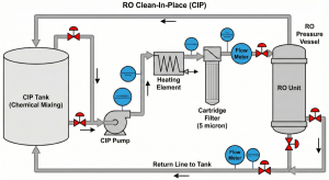
Field Execution Procedure: Critical Parameters to Maintain
In providing reverse osmosis CIP services, field execution requires high discipline regarding process parameters. Errors at this stage, such as rapid depressurization or overheating, can destroy membrane elements in seconds.
Temperature & pH Control: The Keys to Reaction Success
According to the Arrhenius equation, the chemical reaction rate increases with rising temperature. Therefore, CIP solutions are usually heated. However, membranes have thermal limits.
-
Optimal Temperature: Generally 35°C – 40°C.
-
Warning: Do not exceed 45°C as it can cause physical compaction of the membrane leaves’ structure.
pH control must also be done in real-time. During circulation, the solution’s pH will change (for example, acid pH will rise when reacting with limescale). Technicians must add acid/base gradually to keep the pH at the target set-point so the dissolution reaction continues.
Flow Rate & Circulation Time: Preventing Telescoping Damage
The goal of circulation is to create sufficient hydraulic turbulence to “sweep away” dirt that has been softened by chemicals, but at low pressure.
-
Pressure: Must be low enough (usually 20-60 psi) so that permeate production does not occur. If permeate flows out during cleaning, dirt will actually be pushed deeper into the membrane (re-fouling).
-
Flow Rate: Referring to technical manuals like the FilmTec™ Technical Manual, the recommended flow rate per pressure vessel (8-inch) is around 35-40 GPM (9-10 m³/hour).
An excessively high flow causes telescoping, a condition where the membrane roll is physically pushed out, damaging the anti-telescoping device (ATD).
Advanced Technical References:
Post-Cleaning Evaluation: Performance Restoration Verification
After the cleaning instruction for the RO membrane is fully executed, including the flushing stage with permeate water to remove chemical residues, the verification stage is mandatory.
Membrane Integrity and Conductivity Check
The system must be restarted gradually (soft start). Record the data once conditions are stable (usually after 30-60 minutes of operation).
-
Flow Restoration: NPF must return close to the baseline value (recovery target >90-95%).
-
Quality Check: Check permeate conductivity. If conductivity spikes drastically post-cleaning, there is a possibility of O-ring damage or an oxidized membrane due to incorrect chemical selection or extreme temperatures.
Why is Using Mizui Osmosa's Professional Services Safer?
The reverse osmosis CIP procedure involves handling hazardous chemicals and narrow technical parameters. Risks such as exothermic acid-base mixing, permanent membrane damage due to extreme pH, and system failure caused by telescoping are real.
PT Mizui Osmosa Teknovasi offers
reverse osmosis CIP services with an engineering-first approach. We don’t just “wash,” we perform:
-
Membrane Autopsy (if necessary): To determine specific foulant types in the laboratory.
-
Custom Chemical Formulation: Compounding inhibitor and chelating agent concentrations according to site conditions.
-
Mobile CIP Unit: Fully equipped gear with integrated heating and microfiltration.
By entrusting the maintenance of your filtration assets to experts who understand the science behind polymers and hydrodynamics, you secure your plant’s long-term investment.